![]()
![]()
![]()
![]()
The following equipment is used in the field of materials characterization:
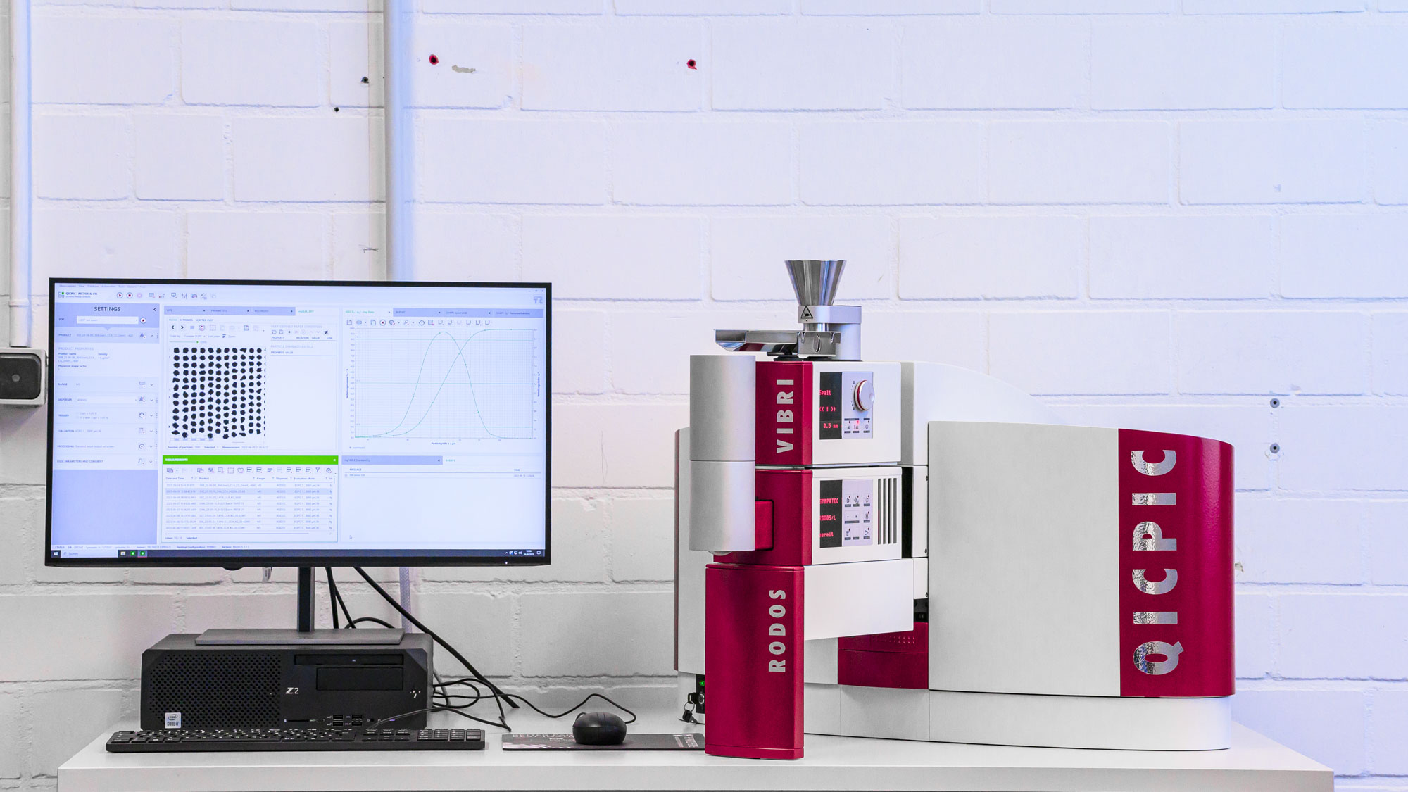
The particle analyzer QICPIC is used to measure metal powder particle size distributions and shape parameters. By using dynamic image analysis, it is possible to view the contour of each individual powder grain and to determine data such as sphericity or the circumference. The material to be measured is fed by the VIBRI dosing unit with a constant mass flow. With the RODOS dry dispersing system, the powder is accelerated through the measuring cell by means of dry compressed air, allowing agglomerates to be broken up and reproducible measurements to be taken.
Key data
Application
Funded by the Deutsche Forschungsgemeinschaft (DFG) - 470572383 and the federal state of North-Rhine-Westphalia

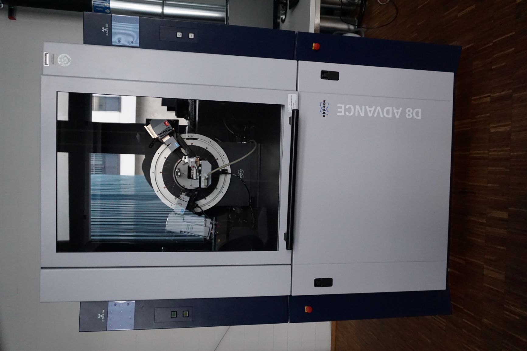
X-ray diffraction (XRD) is based on the diffraction of high-energy radiation at the crystal lattice. The regular structure of the crystal acts as a diffraction grating for the X-rays. The diffraction phenomena that occur (diffraction reflections) contain information about the atomic arrangement of the crystal. This information can be used to make statements about phases contained in materials. In addition, X-ray diffraction experiments with a heating chamber (up to 1200°C) are possible.
Technical specification
Application

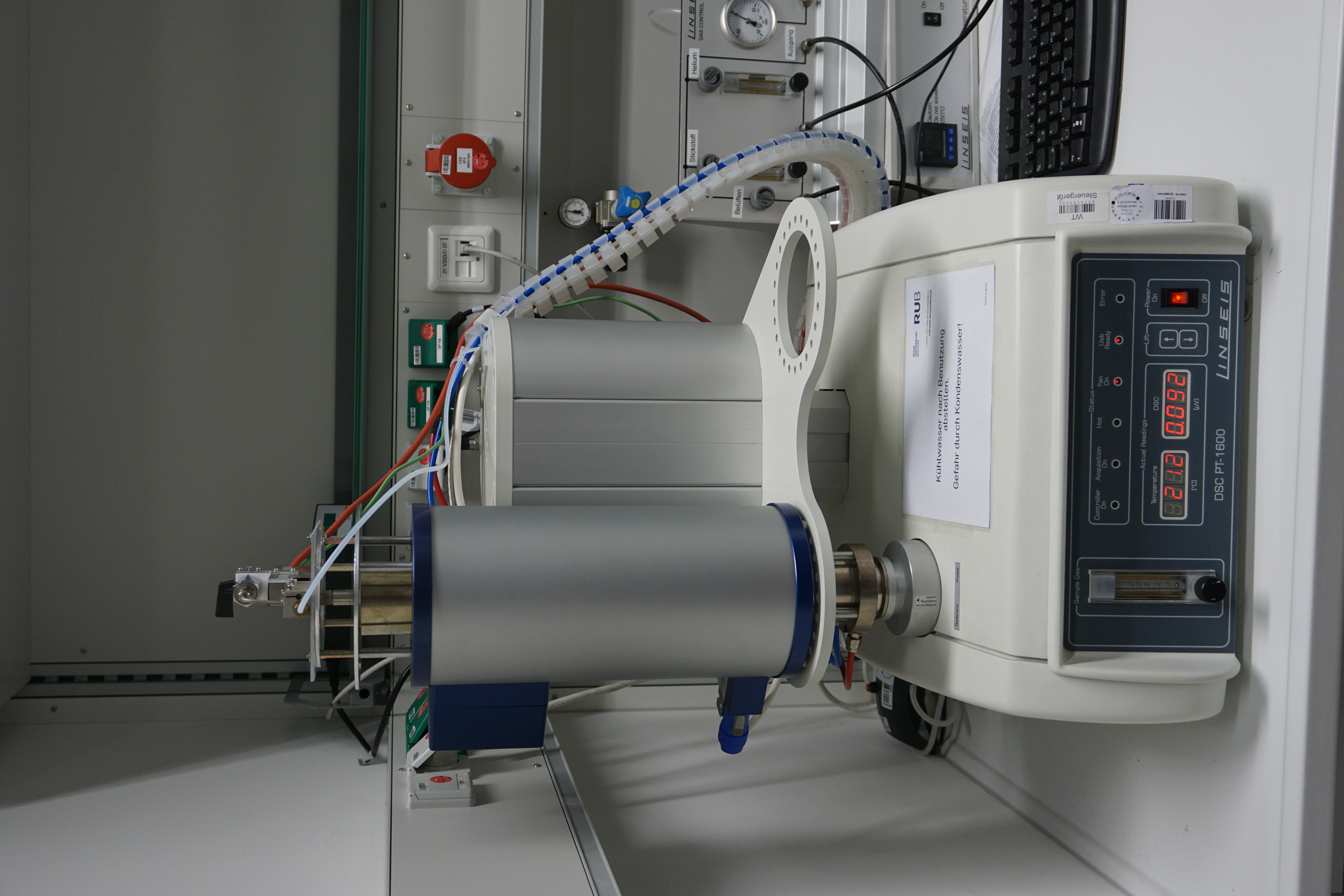
The high-temperature Differential Scanning Calorimeter (DSC) LINSEIS HDSC PT 1600 from Linseis Messgeräte GmbH can be used to perform both DSC and DTA investigations (Differential Thermal Analysis). By means of a DTA, the amount of heat absorbed or released can be determined by comparison with a reference sample. The amount of absorbed heat changes, for example, during phase transitions in the sample. In a DSC the temperature difference is also used to infer a heat flow as a measurand allowing caloric quantities (heat capacity) to be measured.
Technical specification
Application

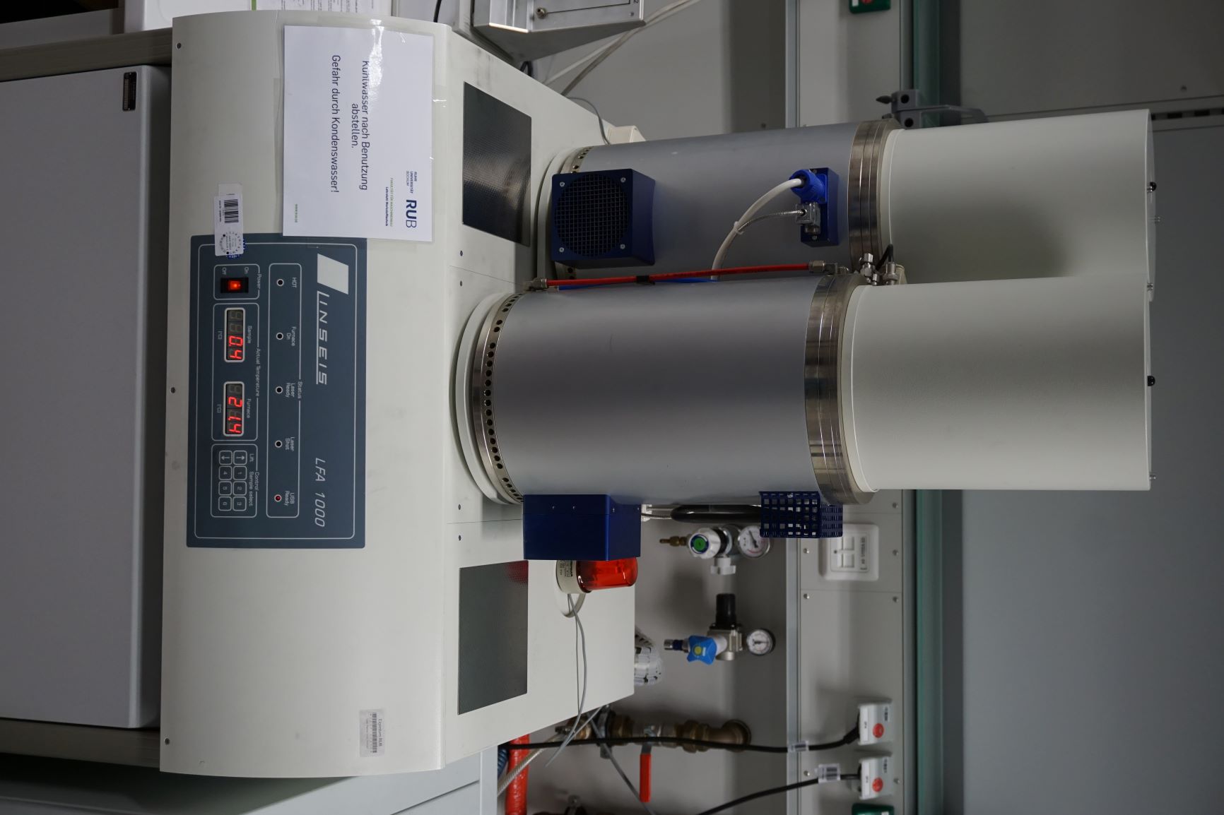
By use of the LaserFlash LFA 1000, the thermal diffusivity of samples can be measured in the temperature range from -100°C to 1000°C. In the LaserFlash method, one side of the sample is heated by a laser. The temperature of the sample is measured on the opposite side of the sample without contact, resulting in a time-temperature profile dependent on the thermal diffusivity.
Technical specification
Application

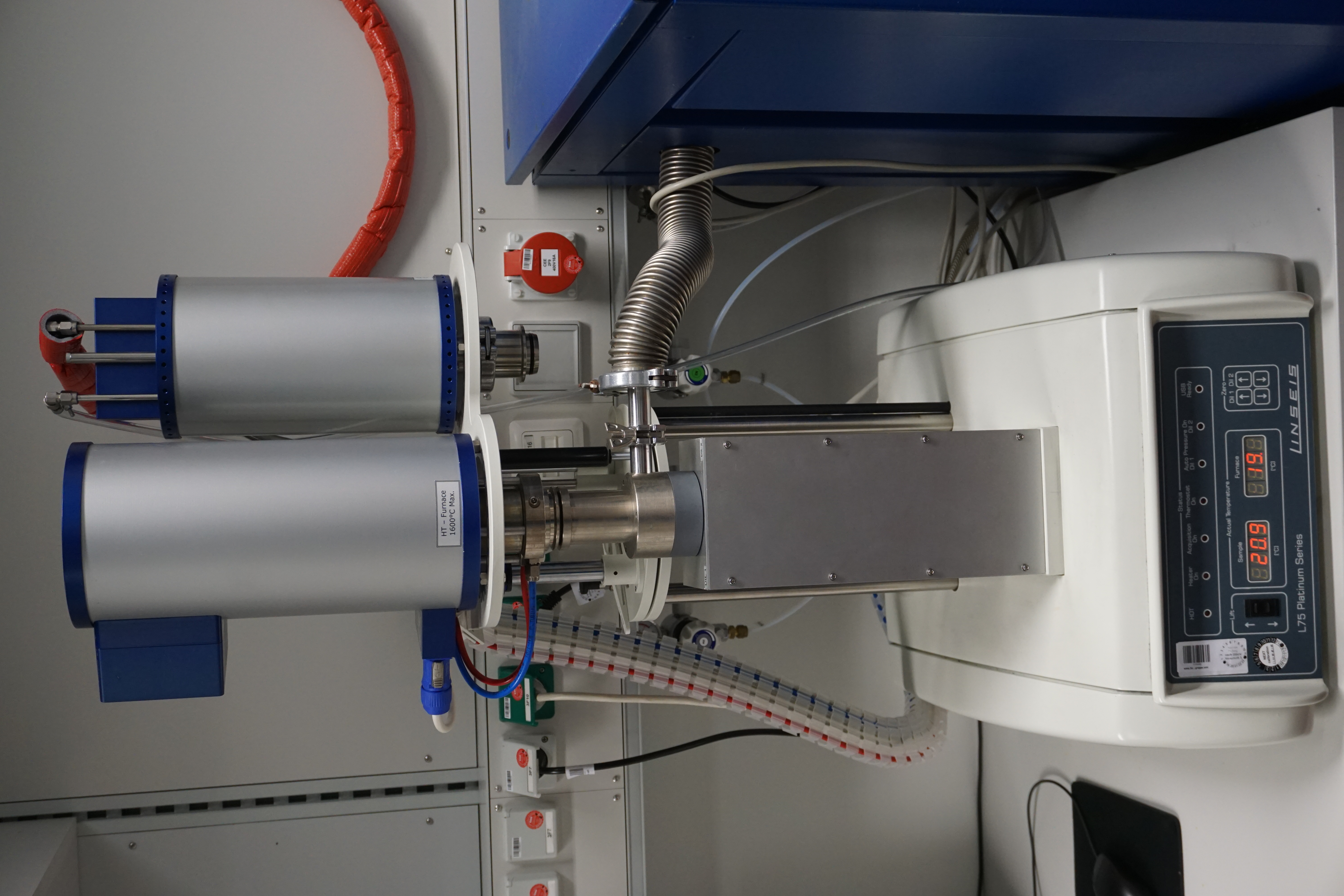
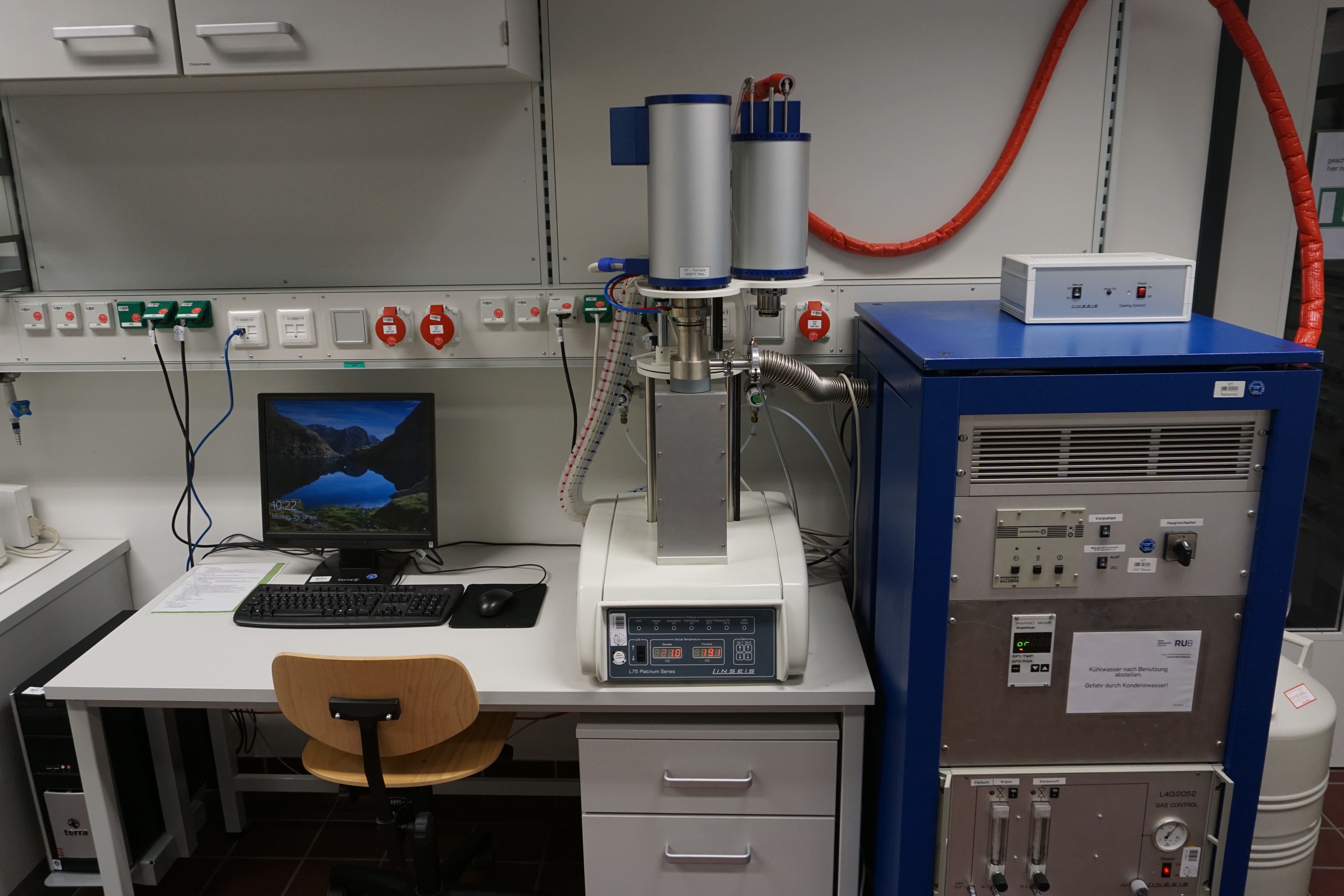
The vertical dilatometer L75V-PT from Linseis Messgeräte GmbH can be used to measure the temperature-dependent expansion behavior of various materials. The special feature of this dilatometer, due to its vertical design, is that solid, liquid and powder materials can be examined. Thus, in addition to the typical application of dilatometers for determining transformation temperatures, it is possible to determine shrinkage processes during a sintering process. Furthermore, it is possible to investigate escaping gases by means of a residual gas analysis during the measurement. The sample is heated by a built-in furnace chamber.
Technical specification
Sample geometries:
Application


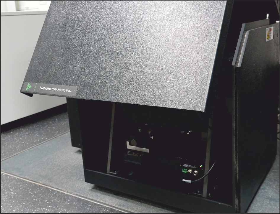
The iMicro from Nanomechanics Inc. is a device for instrumented indentation testing in a wide range of loads up to 1000 mN. It allows determination of Young's modulus in addition to determining the hardness of individual microstructural phases or creating fine resolution hardness curves or mappings. The method of Oliver and Pharr, in which the indenter tip oscillates during penetration, allows the unloading stiffness to be determined over the entire penetration depth. This enables penetration depth-dependent hardness and elastic modulus determination. Various indenter tips are available, including Berkovich, cube or spherical tips. Due to the comparatively high load that can be applied, the iMicro can be used to generate targeted cracks by penetrating the indenter tip in brittle materials such as hard phases or ceramics. Therefore, the fracture toughness of individual phases can be determined via subsequent image analysis. The positions to be indentated are selected by an optical microscope integrated in the iMicro.
Technical specification
Actuator:
Controller:
Application

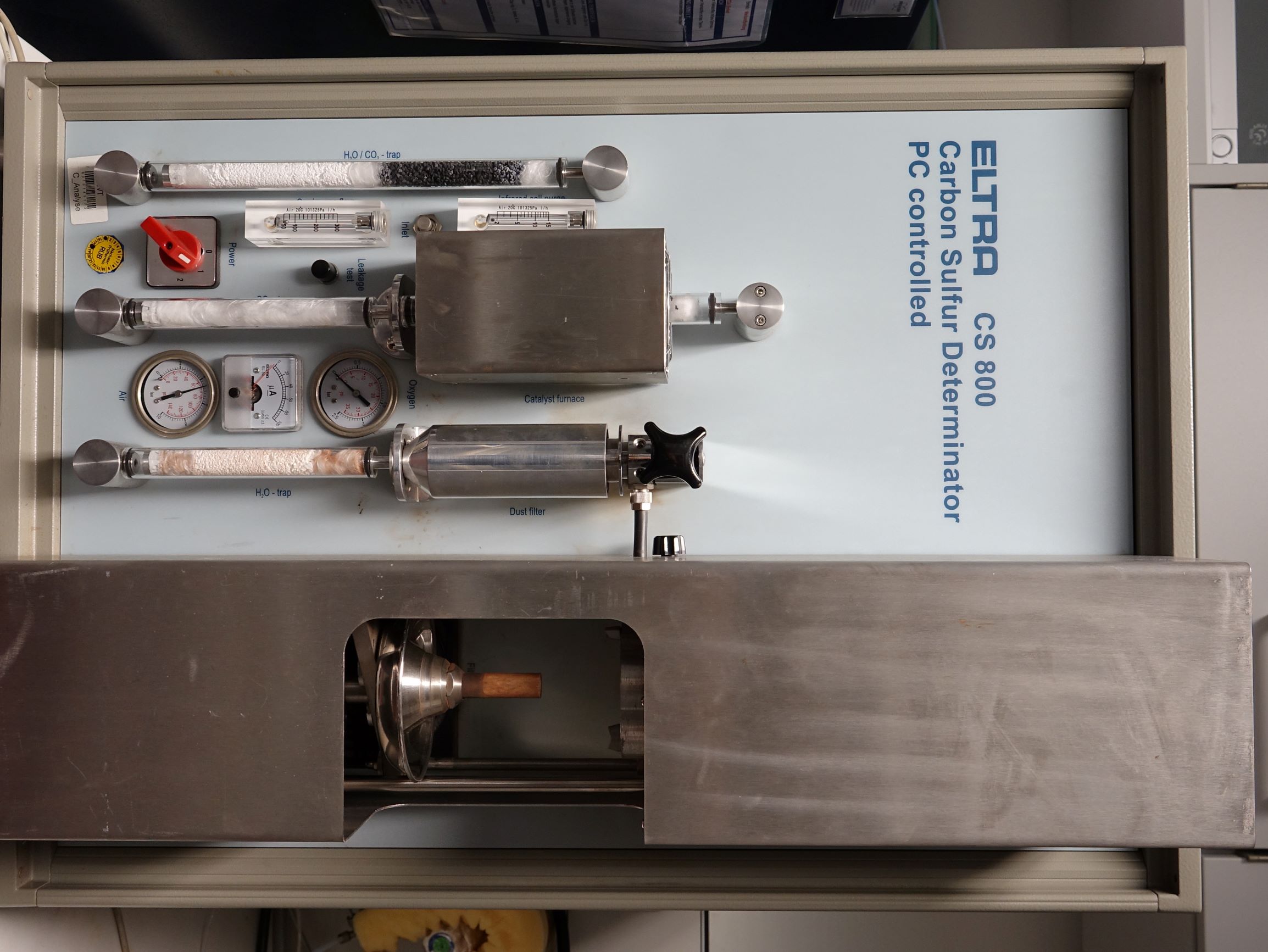
The ELTRA CS 800 elemental analyzer enables the determination of carbon and sulfur content of inorganic samples. The samples are combusted in ceramic crucibles under a stream of oxygen (carrier gas hot extraction). The carbon and sulfur contents of the samples are determined by analyzing the combustion gases CO2 and SO2 in infrared measuring cells. The measuring range extends from a few ppm to several %. For this purpose, several measuring channels can be calibrated simultaneously to different measuring ranges in order to increase the precision of the analysis. Due to the combustion, the samples to be analyzed are destroyed. The mass of the samples should be in a range around 0.5 g for the analysis.
Technical specification
Application

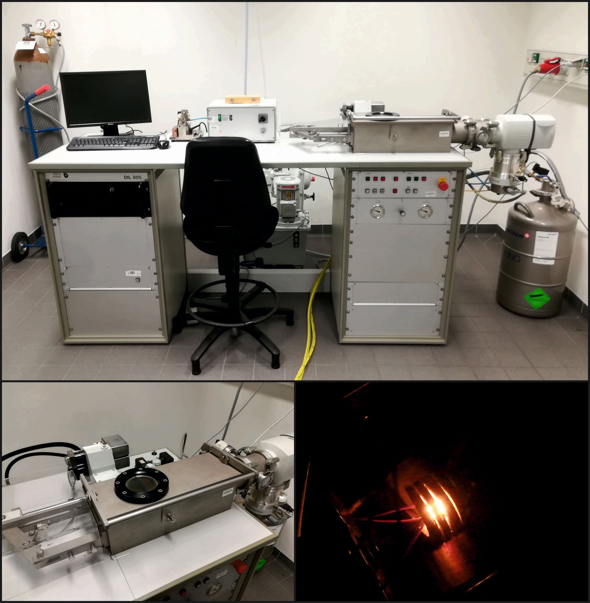
Utilising the stationary DIL 805 quenching and deformation dilatometer (TA Instruments) phase transformations during specific heat treatment can be tracked. The dilatometer operates in two different modes (quenching and deformation).
Quenching dilatometer
In this set-up a metallic solid or hollow sample is inductively heated under vacuum, inert gas or ambient atmosphere to a defined temperature level at a defined heating rate and then continuously cooled at different (linear or exponential) rates by gas stream. Phase transformations of the alloy during heat treatment are evident from abrupt change in sample length. Time-temperature austenitization (TTA) and time-temperature transformation (TTT) diagrams can be generated for the material under investigation by using a variety of heating and cooling rates.
Deformation dilatometer
Using the deformation module, a variety of deformation speeds, forming forces with freely selectable intermediate steps are imposed on a full specimens at the temperature of choice. This allows the simulation of forging or rolling processes under realistic conditions. Subsequently, as with the quench dilatometer, controlled cooling is carried out to determine time-temperature diagram after hot forming.
Further applications are the investigation of creep and relaxation processes at high temperatures.
Technical specification
Quenching dilatometer
Deformation dilatometer
Application

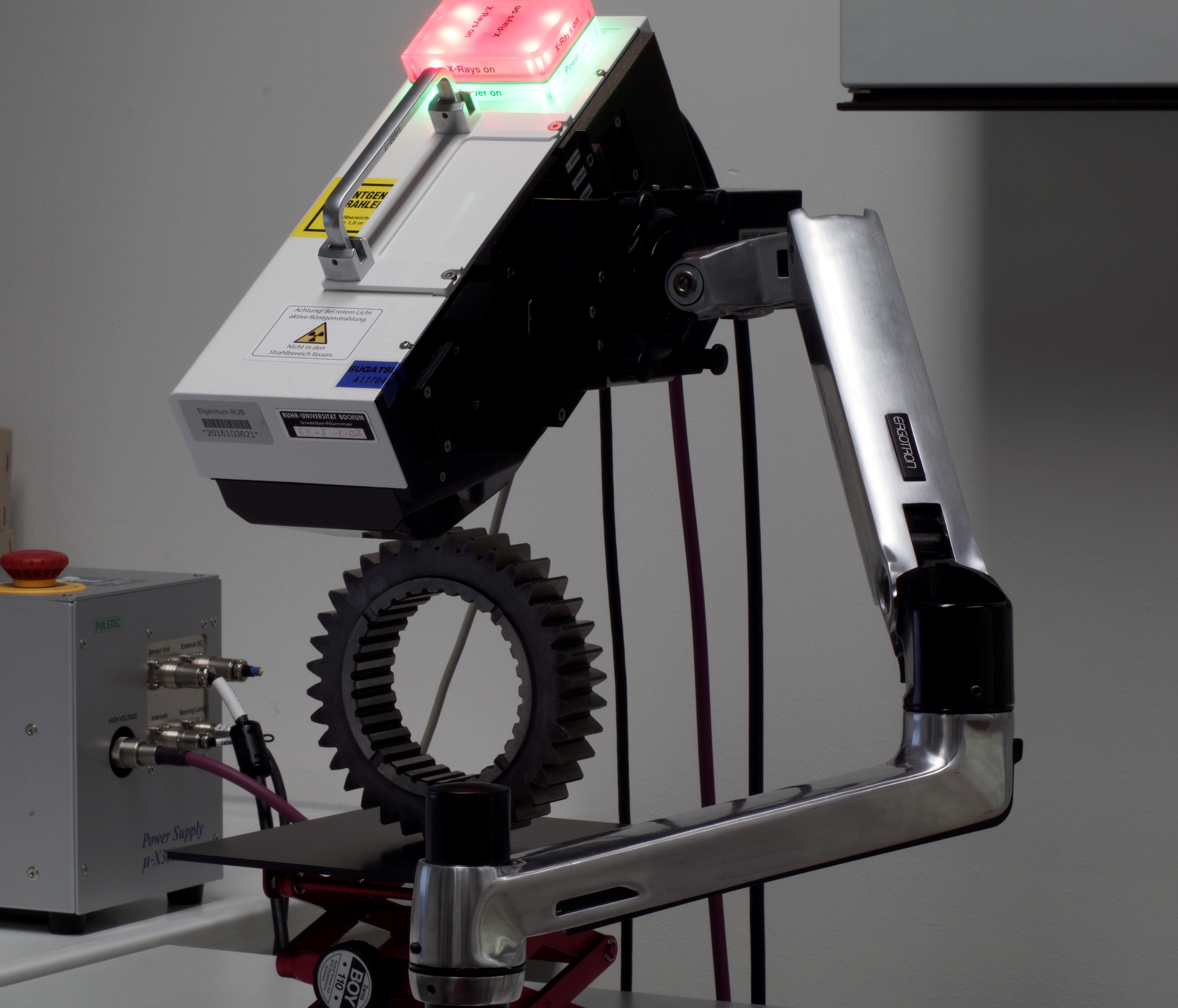
The mobile X-ray diffractometer (XRD: X-Ray Diffraction) Pulstec µ-X360n is based on the diffraction of X-rays at the net plane arrays in the three-dimensional periodic lattice of crystals. Under certain conditions (wavelength of the X-ray radiation, grid spacing), each grid plane produces constructive interference and causes a diffraction cone, the so-called Debye-Scherrer ring. Using the cos α-method, the detection of this Debye-Scherrer ring can be used to infer the strain in the component and, given a known modulus of elasticity, the existing (inherent) stresses can be calculated.
In addition, it is possible to detect a Debye Scherrer ring of the austenitic phase by adjusting the measuring angle. Subsequently, a fully automatic measurement of the residual austenite content can be carried out by evaluating the reflection intensity ratios.
Technical specification
Application

The mobile Feritscope MP30 is used to determine the ferrite and deformation martensite content in austenitic alloys.
In this fast and non-destructive measuring method, an alternating magnetic field is generated by an iron core probe with a low-frequency alternating current. This alternating magnetic field is amplified by magnetic components (ferrite, delta ferrite, deformation martensite, etc.) in the steel, which is detected as voltage. With the help of this interaction between the generated alternating magnetic field and the magnetic components in the otherwise non-magnetic austenitic alloy, the magnetic content can be determined in % by volume.
Technical specification
Application
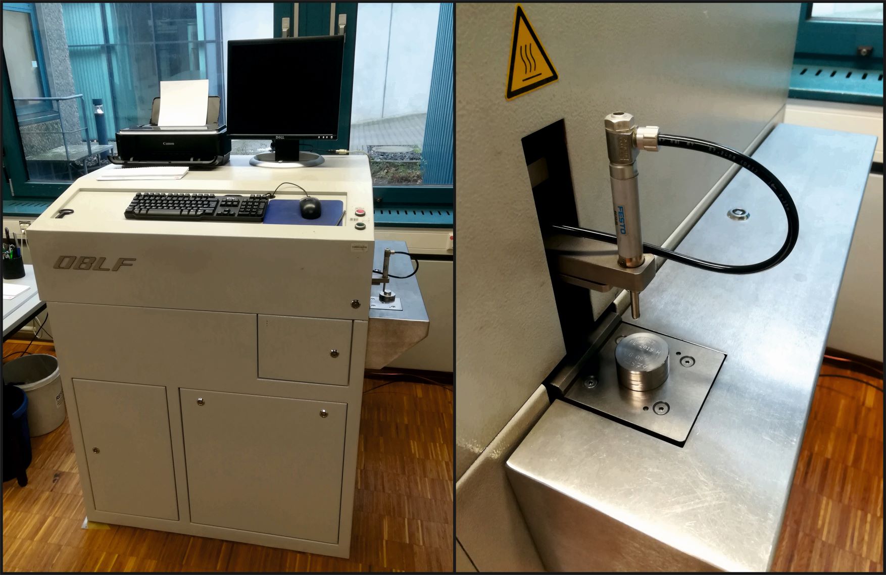
The stationary Optical Emission Spectrometer (OES) OBLF-QSG750 is used to determine the complete chemical analysis of metallic alloys.
In this method, sample material from the alloy to be analysed is vaporised by a spark discharge and the atoms and ions thus released are excited to emit radiation. The entire emission spectrum is then divided into individual, element-specific spectra and quantitatively evaluated.
Technical specification
Application

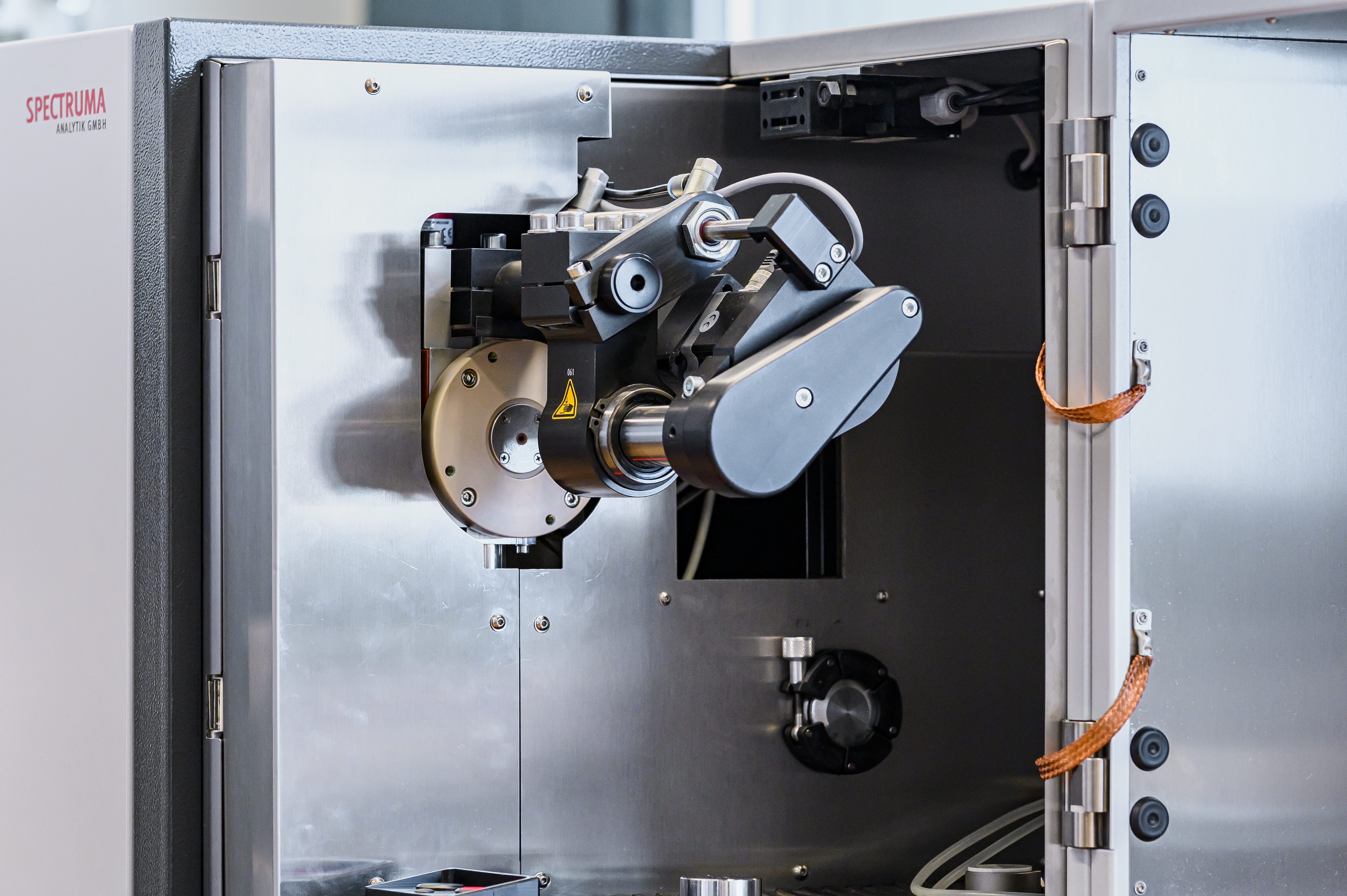
The glow discharge spectrometer is an analytical instrument for the quantitative and qualitative determination of the chemical composition of metallic and non-metallic solid samples. Due to the stable glow discharge source, depth profile analysis as well as bulk analysis of samples can be performed. During the analysis the sample is atomized and the sputtered atoms emit light from the excitation source. This light is split into its spectral components. The spectral lines specific to the individual alloying elements are registered and evaluated by CCD sensors.
Technical specification
Application
Funded by the German Federal Ministry for Economic Affairs and Energy (BMWi, now: Federal Ministry for Economic Affairs and Climate Action, BMWK). The glow discharge spectrometer was acquired in 2020.


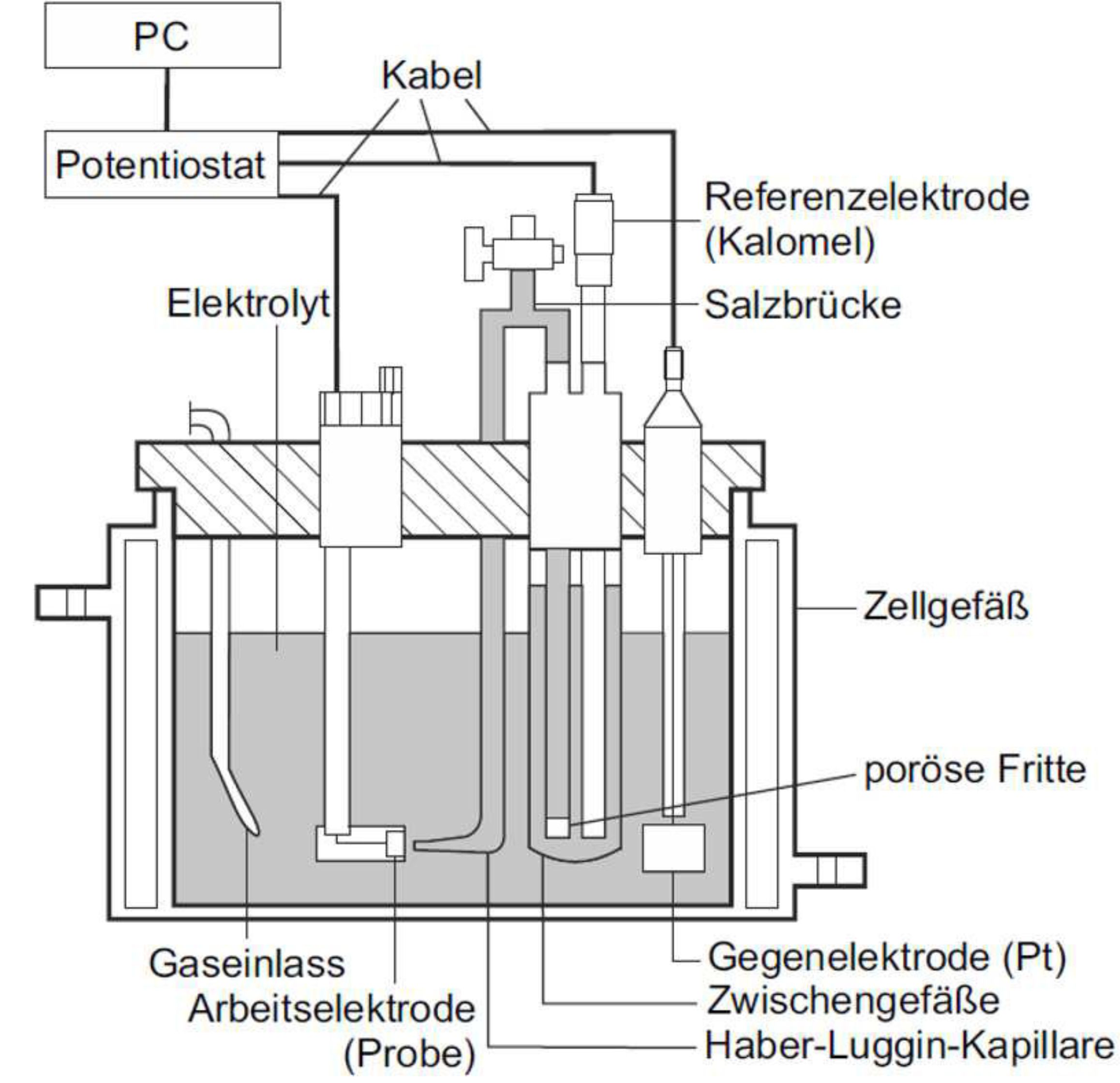
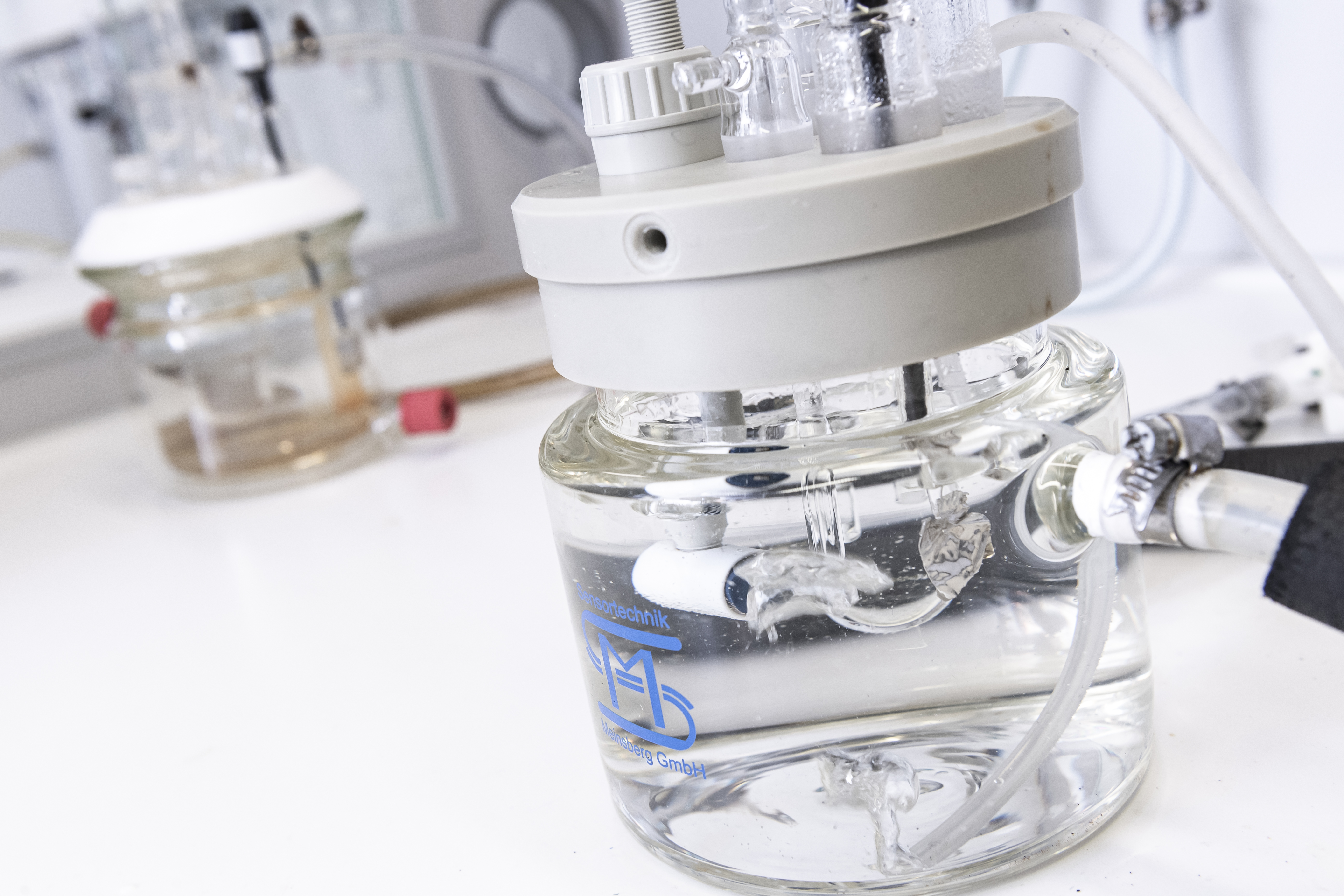
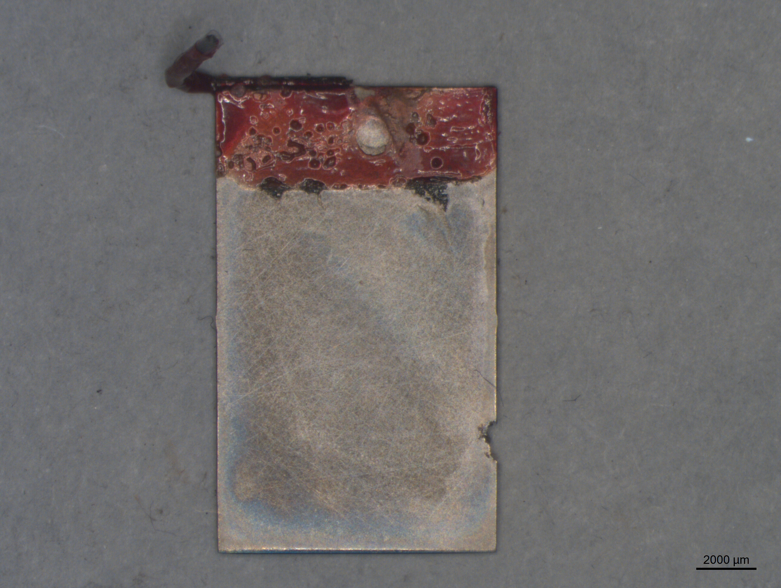
Two three-electrode corrosion measuring cells are available for investigating corrosion properties. In the former, measurements are carried out in dilute sulfuric acid, in the latter in 0.9% NaCl solution. In addition, it is possible to flush the electrolytes with a gas or to heat them up. The measurements performed are used to characterize different corrosion properties. For example, the open circuit potential (OCP) and break-through potential (BTP) measurements, Tafel measurements as well as electrochemical impedance spectroscopies can be performed. The data are recorded via a potentiostat and can be subsequently processed and evaluated on a computer.
Technical specification
Application


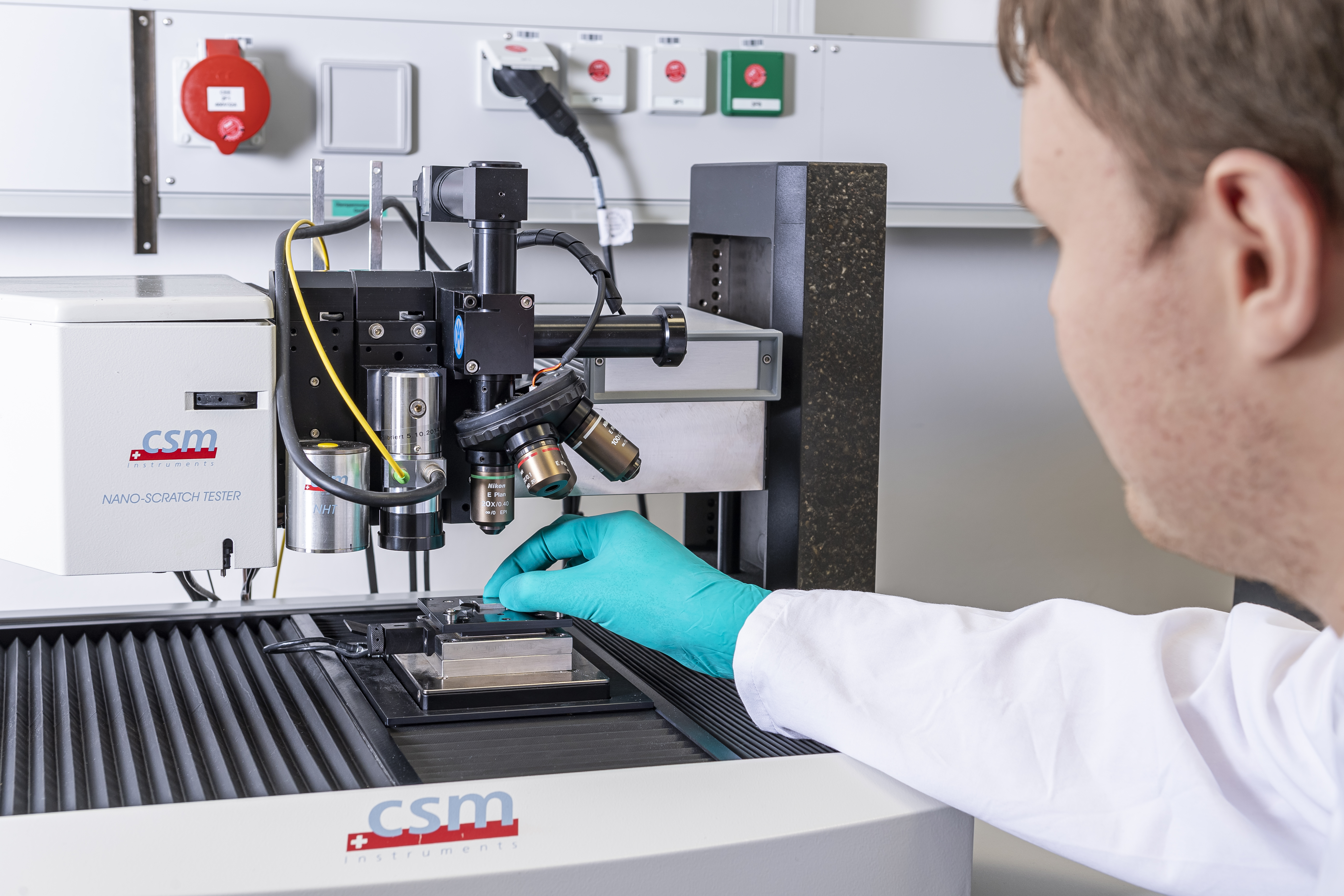
The experimental setup is built on an open platform, which has a cross table that can be moved in the x, y and z directions, an optical microscope, a nanoscratcher and an atomic force microscope (AFM).
The light microscope can be used to select the exact position at which a sample is subsequently scratched by a - usually cone-shaped - diamond tip using the nanoscratcher. For this purpose, the tip is pressed onto the sample with a defined force via a double bending beam, whereby the normal force, transverse force (frictional force) and the penetration depth are permanently measured. Scratch tests can be run with different parameters as well as indenters. Thus, the load can be kept constant or increase linearly as well as stepwise. A pre-scan with low load can scan the surface topology before the actual scribing. A post-scan can distinguish permanent and reversible surface changes.
The atomic force microscope (AFM) offers the possibility of imaging surfaces with very high resolution. The surface topology is measured in the x, y and z directions. The result is precise coordinates of the topology in all three spatial directions, which can be evaluated in various ways using suitable software.
Technical specification
Optical microscope:
Nanoscratcher:
AFM:
Application

Copyright © Lwt 2026
Last update: Feb 06, 2026