![]()
![]()
![]()
![]()
The following equipment is available at the LWT for mechanical material testing:
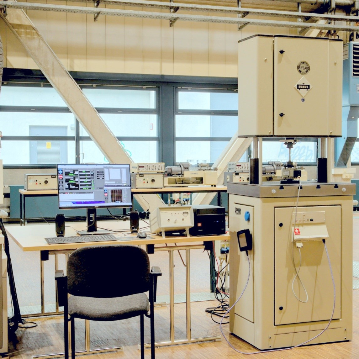
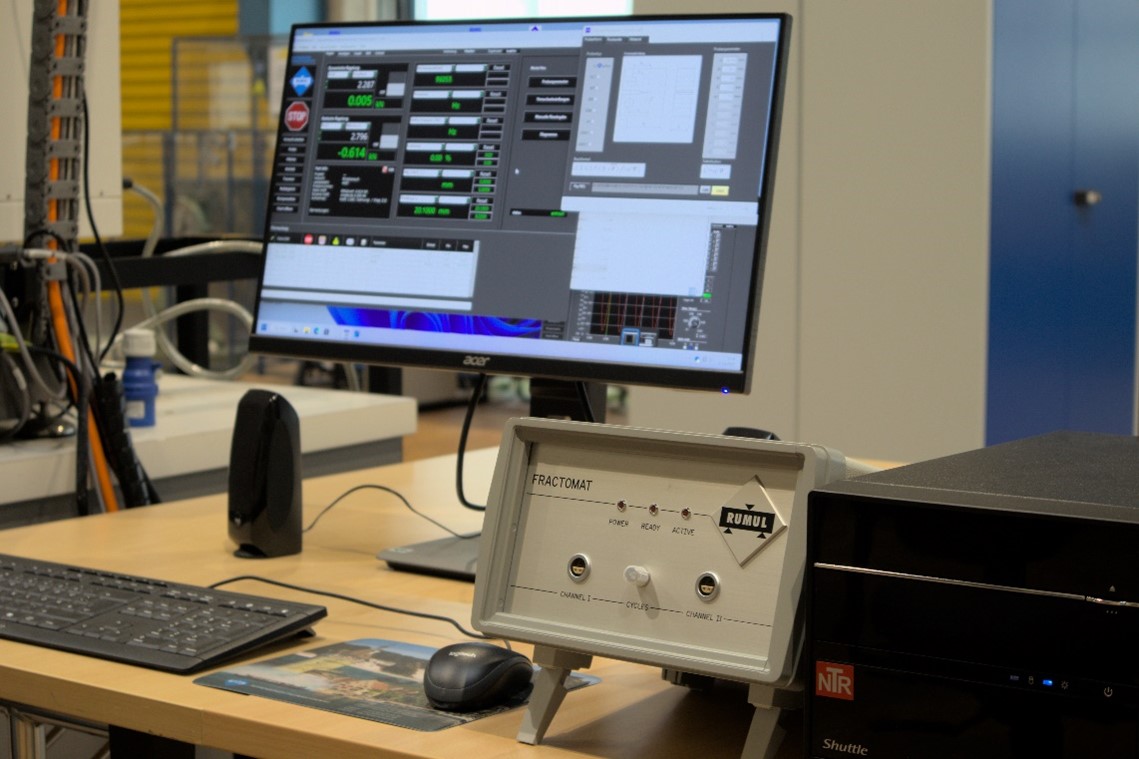
The RUMUL Mikrotron resonance testing machine can be used for dynamic tensile, compression and bending tests on a wide range of specimen shapes. Due to its ability to detect a formed crack by the drop of the material's natural frequency, the machine can automatically adjust the applied test load. This allows very precise and reproducible crack generation on fracture mechanics specimens, as well as a wide variety of test shapes for crack growth measurement. Using stick-on crack measurement foils and an additional analyzer (Fractomat), the crack length can be measured, recorded and processed in-situ, for example to automatically adjust the applied load in a ΔK-controlled test. The high test frequency of up to 250 Hz allows testing of large series of test specimens, as well as testing in the UHCF range (UHCF, Ultra High Cycle Fatigue). Due to the high measuring accuracy, even in small load ranges from 10 to 100 N, the testing machine is able to reliably test even small specimens, which have been manufactured by additive manufacturing, for example.
Technical data
Application


The single-pass pendulum serves as a model test to evaluate the machinability of materials and was constructed from a notched hammer at the chair. A specimen is clamped in the holder on the force measurement platform and, after release of the cranked-up arm, a chip of a controlled chip depth is removed by an indexable insert while normal and tangential forces are measured. The energy required for chip formation can then be calculated by integrating the tangential force component over the path, or by calculation from the difference between the drop and climb angles of the pendulum arm. In this way, a simple geometry can be used to model the resistance of materials to cutting and to study chip formation characteristics.
Technical Data
Application

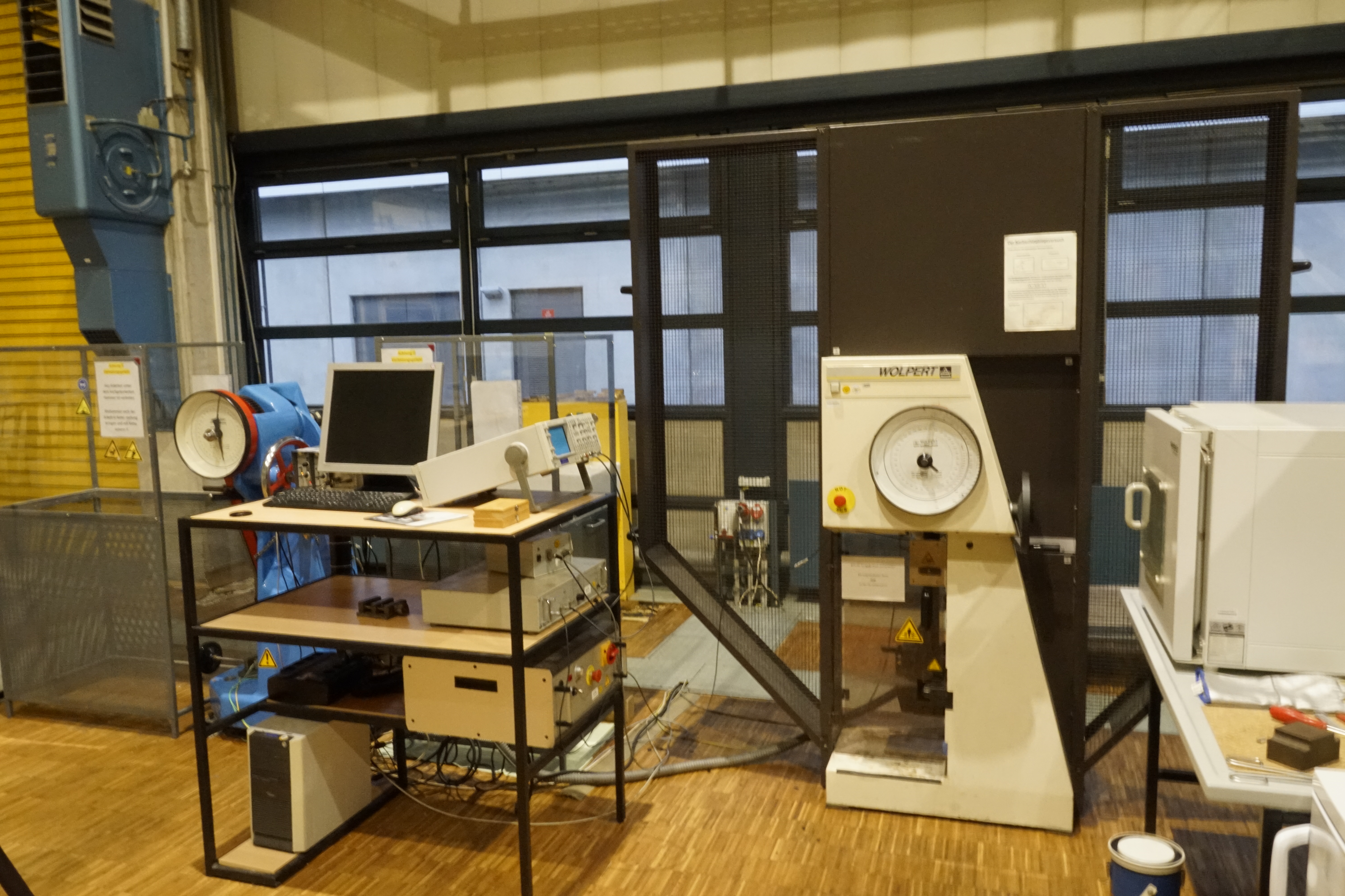
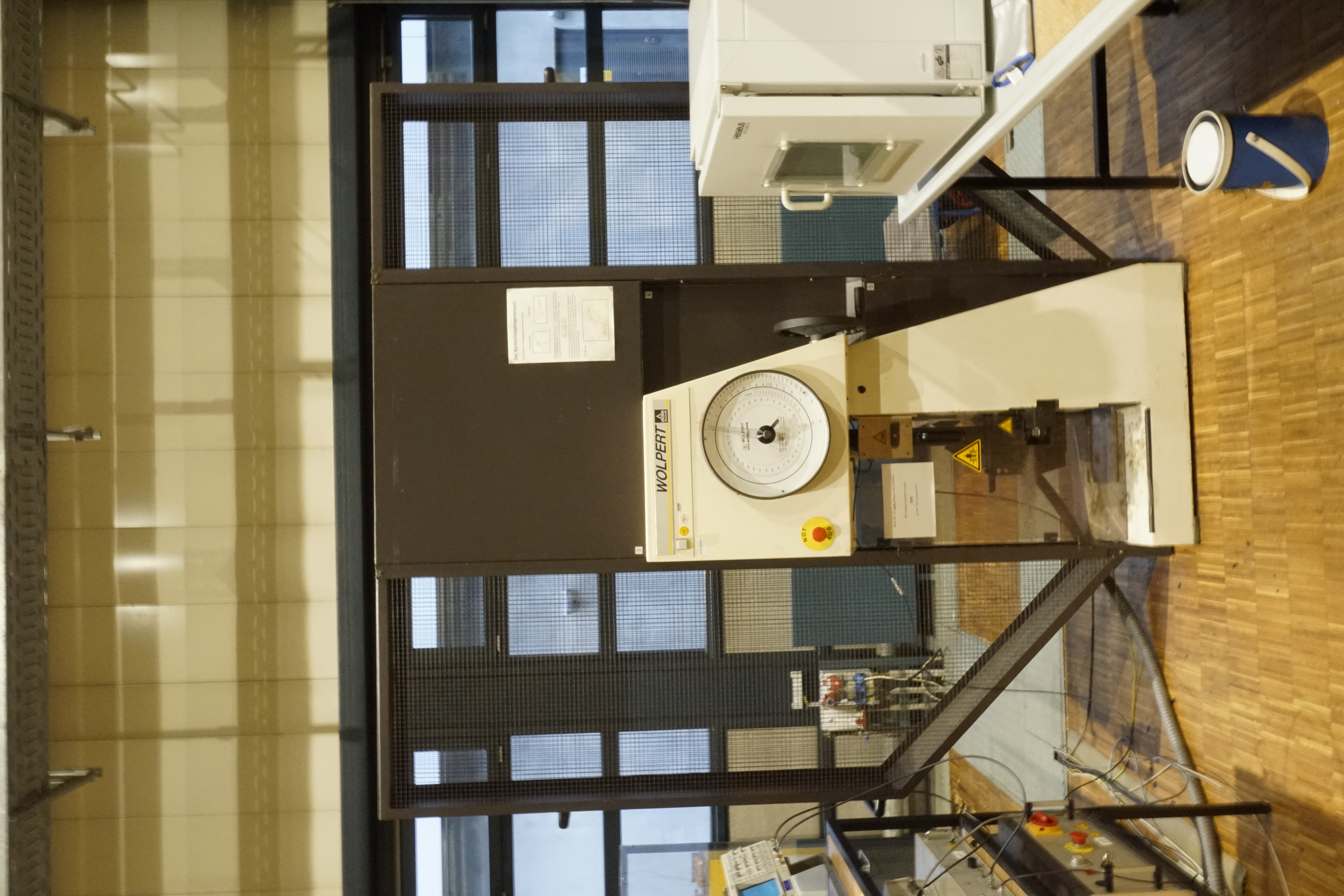
The Wolpert PW 30 pendulum impact tester, equipped with a 150 J or 300 J hammer, can be used to investigate the impact strength of a material. Instrumentation consisting of four strain gauges and a measuring amplifier can be used to measure the applied force during the impact process. A rotary encoder simultaneously records the distance traveled, allowing the impact energy to be calculated from the integration of the force over the distance. The force curves can also provide information about the sequence of specimen failure.
Technical specification
Application


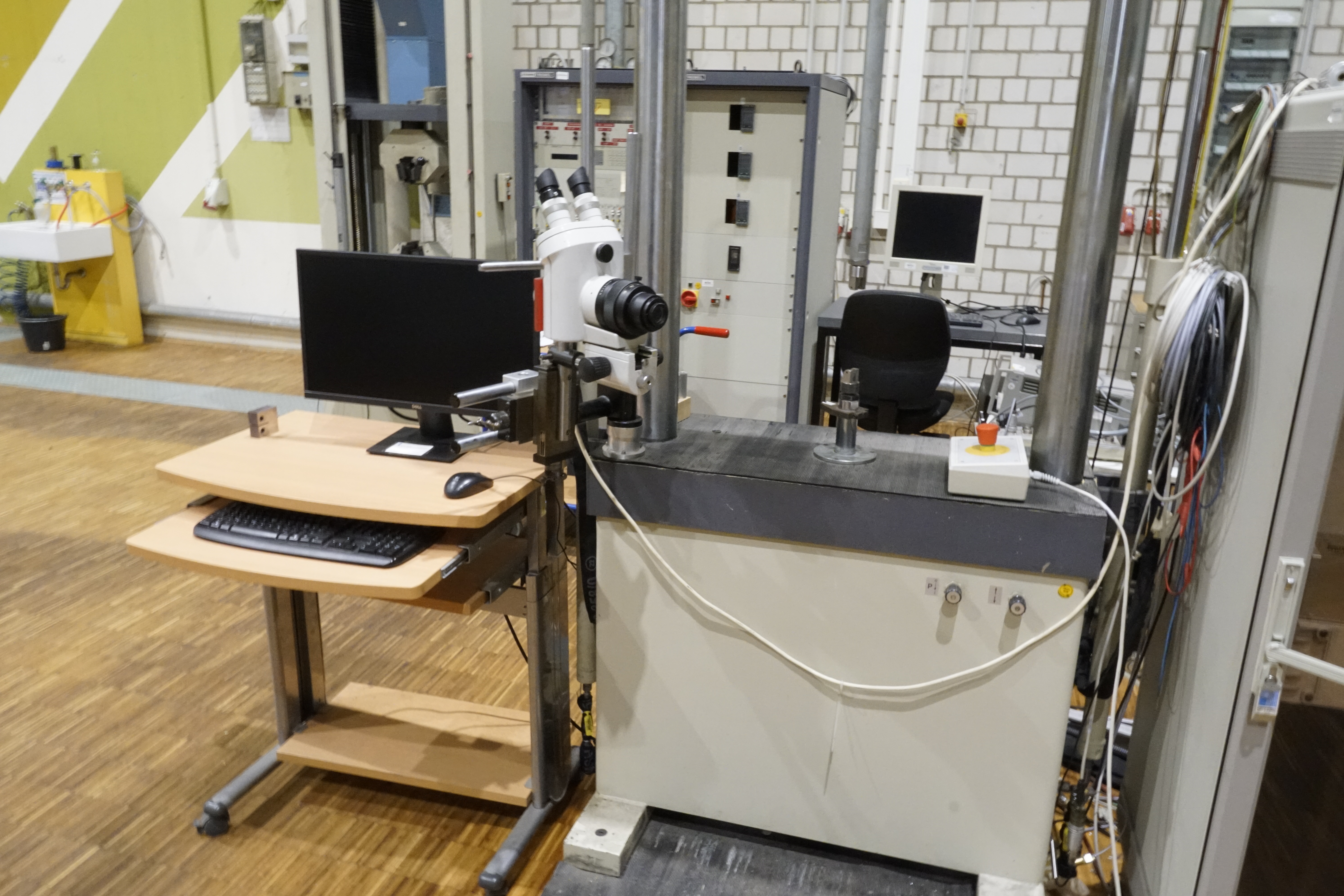
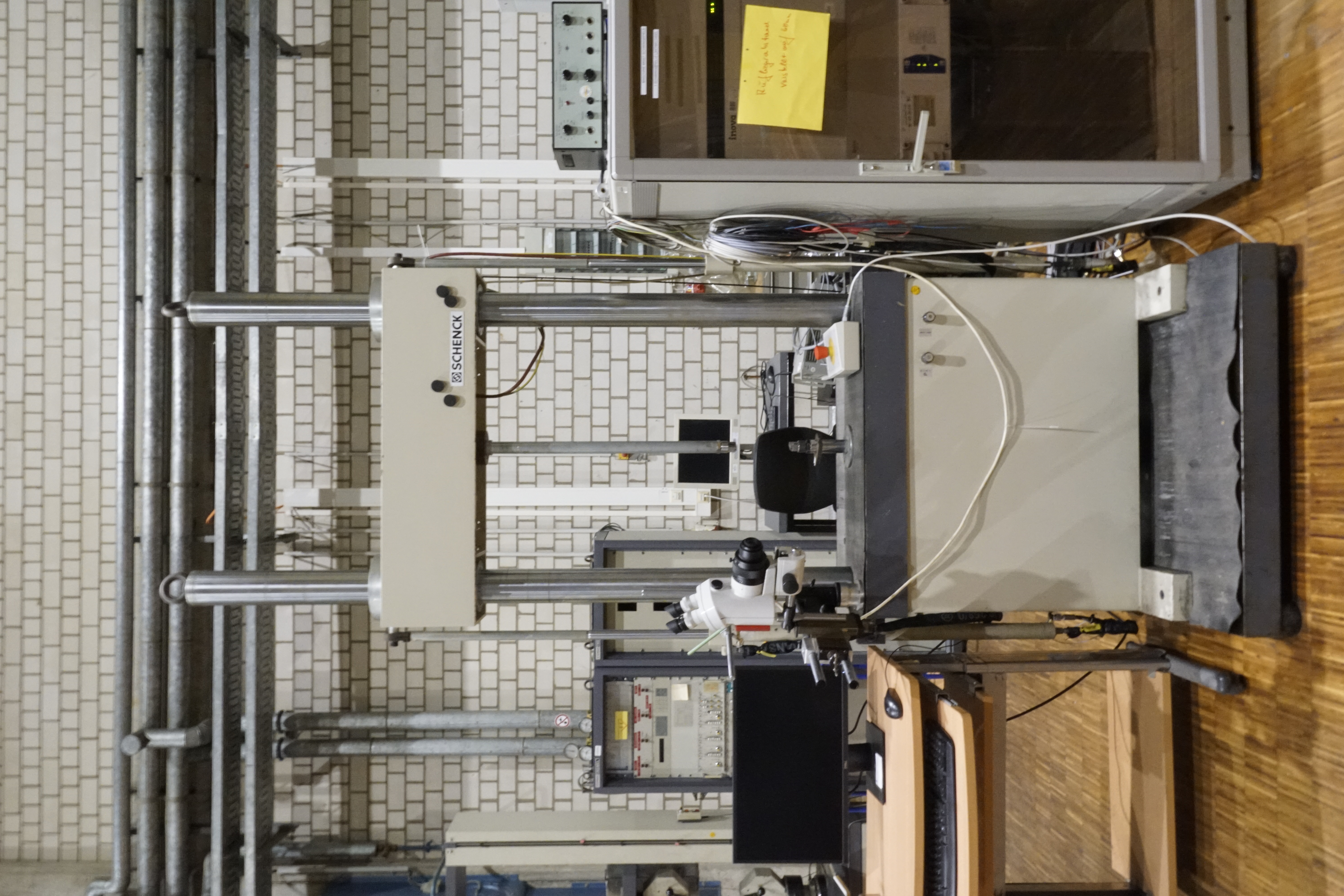
With the servo-hydraulic systems from Schenck of the PC160 and PC400 series, tensile tests, compression tests and bending tests up to 400KN can be carried out. In addition, dynamic tests can be performed. For dynamic tests, a cyclic load is applied with a corresponding test frequency. These can be both rapid load tests in tension or compression and alternating load tests with tension and compression components.
Technical specification
Application


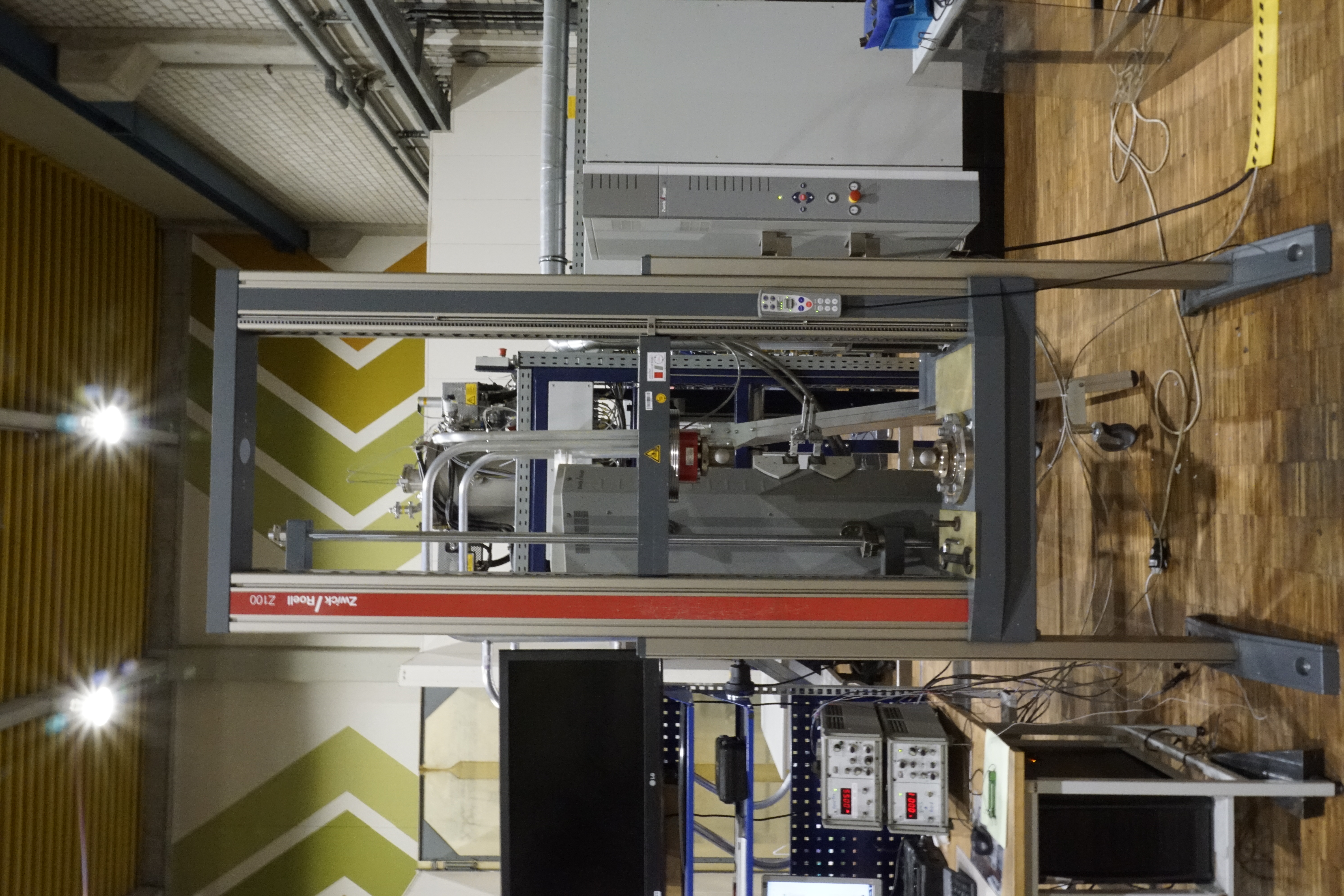
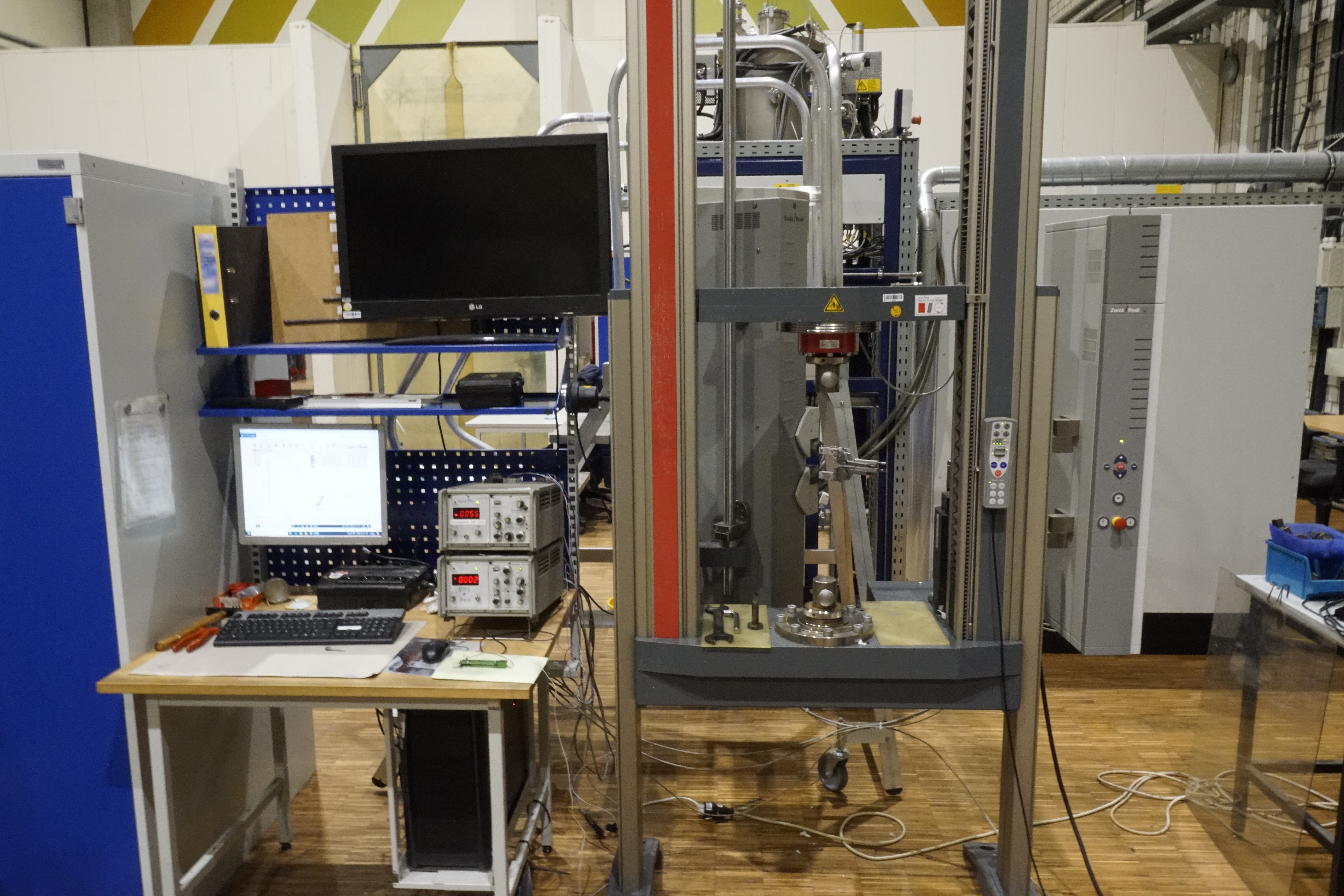
Tensile tests, compression tests and flexure tests can be carried out with the Zwick/Roell Z100 series tensile testing machines. They are only used for static testing, as the force is applied via the spindle within the columns. Due to many years of experience with special specimen shapes, the testable specimen catalog of the Materials Engineering Chair has grown to an astonishing size. The two systems offer the possibility to test at room temperature as well as at depths and elevated temperatures.
Technical specification
Application


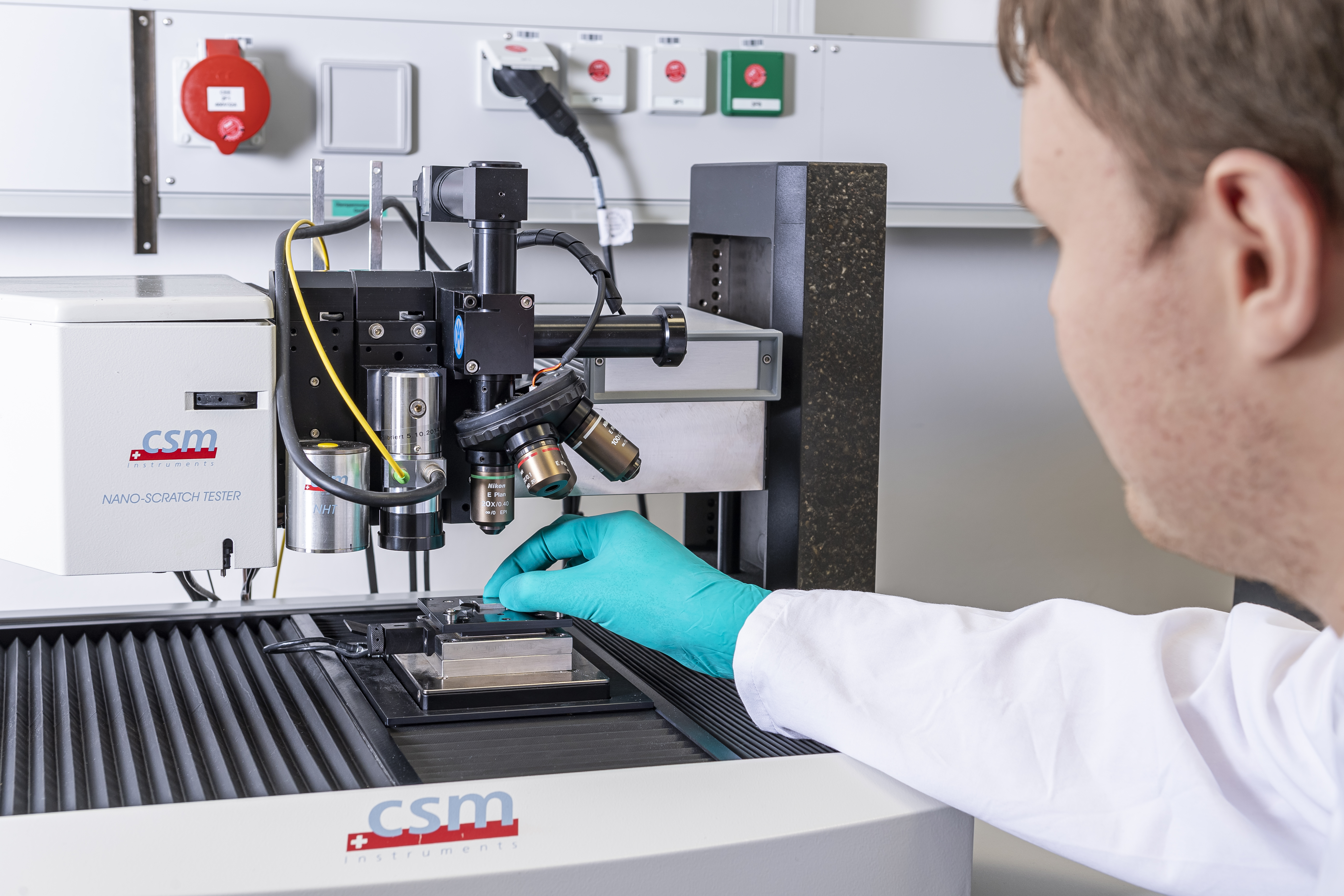
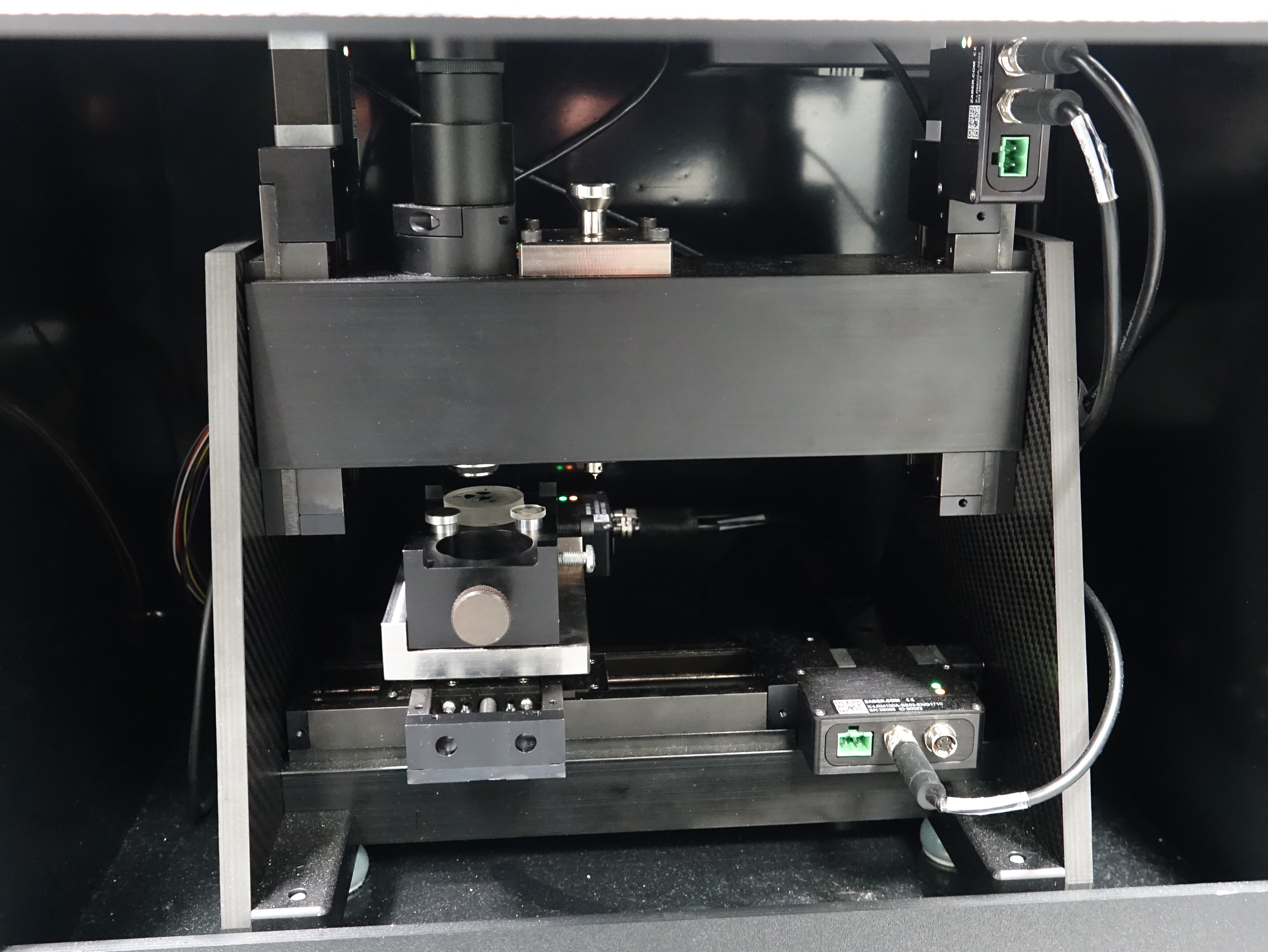
The experimental setup is built on an open platform, which has a cross table that can be moved in the x, y and z directions, an optical microscope, a nanoscratcher and an atomic force microscope (AFM).
The light microscope can be used to select the exact position at which a sample is subsequently scratched by a - usually cone-shaped - diamond tip using the nanoscratcher. For this purpose, the tip is pressed onto the sample with a defined force via a double bending beam, whereby the normal force, transverse force (frictional force) and the penetration depth are permanently measured. Scratch tests can be run with different parameters as well as indenters. Thus, the load can be kept constant or increase linearly as well as stepwise. A pre-scan with low load can scan the surface topology before the actual scribing. A post-scan can distinguish permanent and reversible surface changes.
The atomic force microscope (AFM) offers the possibility of imaging surfaces with very high resolution. The surface topology is measured in the x, y and z directions. The result is precise coordinates of the topology in all three spatial directions, which can be evaluated in various ways using suitable software.
Technical specification
Nanoscratcher:
AFM:
Application

Nanoindentation in a wide range of loads up to 1000 mN. In addition to determining the hardness of individual microstructural phases or creating finely resolved hardness curves or mappings, it also allows the Young's modulus to be determined. The method of Oliver and Pharr, in which the indenter tip vibrates during indentation, allows the unloading stiffness to be determined over the entire depth. This enables indentation depth-dependent hardness and elastic modulus determination. Various indenter tips are available, including Berkovich and cube indenters. Due to the relatively high maximum load, the iMicro can be used to generate cracks in brittle materials, with the aid of which the fracture toughness of individual phases can be determined via subsequent image analysis. The positions to be indentated are selected by an optical microscope integrated in the iMicro.
Technical specification
Application


Copyright © Lwt 2026
Last update: Feb 06, 2026